 SVR S&T Dept.

SIGNALLING NOTES - Chris. Hall
My prompt to write this article is the sound of the last issue hitting the doormat. Issue 193 arrived in good time, givng me six weeks to write the article but I missed the deadline by a few days. Now issue 194 has arrived, so with another six weeks until August 1st, I'll try again.
Some complaints had been made about the main to main crossover at the North end of the station Bewdley being heavy to work (Bewdley North No. 6 points) but we had been expecting the P-Way to replace them 'soon': their work programme now suggested 2023 for this work. As there was a scaffold structure in the Up Main and Back Road (platforms 2 and 3) during the non-running period in January/February this suggested the possibility of single-line working being adopted through the Down Main during February half term week.
These points therefore deserved some attention - in the situation described, they would need to be worked for each Up train - set normal to release the Up Home signal lever, and then set reverse (and bolted and clipped) to allow the Pilotman to admit the train to platform 1. Their reliability of operation would therefore become critical to timekeeping. In the event, the scaffolding through the Up Main was removed before services resumed.
Our examination of the rodding run to these points in January showed that the drive crank underneath the box needed tightening, the lead-off crank was worn, the compensator between the box and 6A points was worn and the compensator between 6A and 6B points was worn. Actually none of this would account for the points being heavy to work and neither would these affect the safety of the signalling system but we made sure that the points were well adjusted so that they would operate correctly (6B points are not often bolted reverse for traffic movements).
The first job was to tighten down the drive crank under the box. This was mounted right over a rolled steel joist supporting the floor and was thus coach bolted whereas most of the cranks were through bolted. Awkward access and hard work, but using two adjustable spanners - a 36" and a 24" - we were able to get about half a turn on each coach bolt. We then asked the Signalman to work the points repeatedly so that we could see whether the crank was secure. We could now relax and watch someone else work hard!
It would be a bigger job to replace the crank and compensators with refurbished equipment held in our stores at Kidderminster. We were planning to replace timbers on the Up Inner Homes but the scaffolding was not installed until 10th March and so the next weekend (6th March) was our opportunity to do this work. Fortunately there was a spare member of station staff, rules qualified, who could act as Handsignalman for the Inner Homes. We checked that we had all the nuts, bolts, crank pins, split pins and tools we would need for the work plus the refurbished crank and compensators.
Points 6 were disconnected with some signals also disconnected to maintain safety. Electrical detection on 5/6A was also disconnected. The point lever could be worked to maintain locking in accordance with Rule 77, but only with our permission as we were working on the rodding. FPL levers 5 and 8 would also be worked to allow the Home signals to be used. The points would have to remain disconnected for a few hours until we had finished the work.
The work itself on each crank or compensator was fairly straightforward - remove the worn base, which was bolted to a steel plate, fit the refurbished base and crank(s) and bolt it down. Again access is fairly awkward but the nuts undid despite having been there for over 40 years - the Whitworth thread is an excellent design - but we did fit new bolts! The compensators were much heavier than the cranks and were further from the box but we were able to manoeuvre a wheelbarrow over the ballast to get them to site. There were enough of us to work on two bases at the same time and it was all the rodding was reconnected by about 2p.m. and were ready to test and adjust the points.
Unexpectedly the lever jammed when being moved from reverse to normal - all this work and the original problem was still there! A very thorough check of the entire rodding run showed that one of the two rollers carrying the drive across the tracks to 6B points was tipping up and jamming. We packed this temporarily (until the afternoon) and were able to adjust the points and book them back on. Finally we could have some lunch!
In the afternoon we visited one of the wagons on the Stourport line and 'withdrew' a concrete base 'from stores'. We had a new roller casting in stock and so replaced the roller and base so that the points would continue to operate smoothly. The worn compensators would need to be sent away for refurbishment (Bridgnorth has since offered to do these on an occasional 'as work permits' basis) as the main pivot pins were too large for us to machine (we would drill out and bush the smaller holes but the two 2" spindles on a large cast base was much too big for our lathes).
The scaffolding on Bewdley North Up Inner Homes was installed on 10th March and so the following weekend we replaced the rear decking - this was fifteen feet above the track and with the access ladder bolted to one of the planks that would need to be replaced, would require scaffolding. We had measured the position of the signal relative to the track and loading gauge and drawn this up to facilitate the supervision of the scaffolder.
 The scaffolding on Bewdley North Up Inner Homes on Sunday 6th March [Photo: C. K. Hall]
The following week the structure was examined, cleaned and painted and the scaffolding was removed just after the Spring Gala. We now had quite a bit of work on hand at Bewdley, refurbishing the worn cranks and compensators we had just replaced (rebushing the pin-joints and main pivot pin) and overhauling the FPL bar hangers we had replaced at Highley. We got an urgent call to Kidderminster that the signalman was having great difficulty unbolting the No. 2 Platform Facing/No. 2 Engine Line points (No. 42) when they were reverse and although he had got them unbolted, it had been a struggle. Leaving the machining half completed we hustled onto an Up train to join our Kidderminster resident. A rather strange fault where the electrical detection box had admitted water and one slide had become just stiff enough to cause the FPL slide to bind and seize. So much mechanical advantage (a signalman on a six foot lever making a 4" movement) but to no avail. A bit of cleaning and lubrication (and, later, replacement of the rain seal) cured this unusual prolem and we returned to our work at Bewdley on the next train.
On Easter Monday the Kidderminster Signalman complained that the FPL which locks the yard points (No. 25) was difficult to unbolt - it was standing mid stroke and delaying some shunting - and the Department attended to find that the track had dropped and the rodding to the FPL was scraping (and sometimes jamming) on the concrete base that supported the detection. This was something to refer to the P-Way for action in the first instance (we could spend all day digging out our concrete base (with all the adjacent rodding disconnected) lowering it an inch or so but that would be treating the symptoms rather than the disease) and with care 25 FPL could still be used. The P-Way later confirmed that their track had not dropped and so their solution was to chip some concrete from our concrete base.
We cannot afford to scrap worn GW compensators (fitting a new BR compensator is a much bigger job than a like for like replacement as the mounting arrangements are different, requiring handsignalling for days or weeks rather than hours) and the bases are too large for us to machine easily at Bewdley. Bridgnorth do have a machine large enough to do this and we have provided a worn example for them to refurbish the main pin and bush the crank to see whether it is the sort of job that can be fitted in on an 'as and when' basis. If not then we will probably have to send them away for refurbishment. We had managed to refurbish one compensator at Bewdley and started a programme of replacing worn ones with refurbished ones - a few months after we had installed it (at Highley) it fell down the bank and was so badly damaged it had to be scrapped.
With several cranks to refurbish, we realised that the more we had to do at one time, the more efficiently we would be able to do it. There had been some complaints about the Down Main to No. 2 Platform Line Facing/No. 1 Platform Line points, otherwise known as the points on the road bridge, at Bridgnorth (No. 12 points) and we had about six refurbished accommodating cranks in stock in our Kidderminster stores. We felt that it might be possible to find some worn cranks at Bridgnorth and therefore did a full survey of the rodding run from the box to 11 (FPL for 12), 12, 13 (FPL for 14) and 14 (No. 2 Platform Line Facing/Engine Shed Sidings). In case you ask, I don't remember the names of every point and signal but look up the relevant lever leads on my signalbox simulation (available from my web site).
This survey showed six worn accommodating cranks, which would conveniently use up our entire stock of refurbished cranks, providing about nine cranks for us to refurbish. It also showed that four compensators were worn, two of which (for 11 and 12) were mounted on the same plate but also showed that that plate needed to be moved some six metres closer to the box. Moving a compensator base is a huge job and would therefore have to wait until January/February when we could have the south end of Bridgnorth booked off for a few weeks.
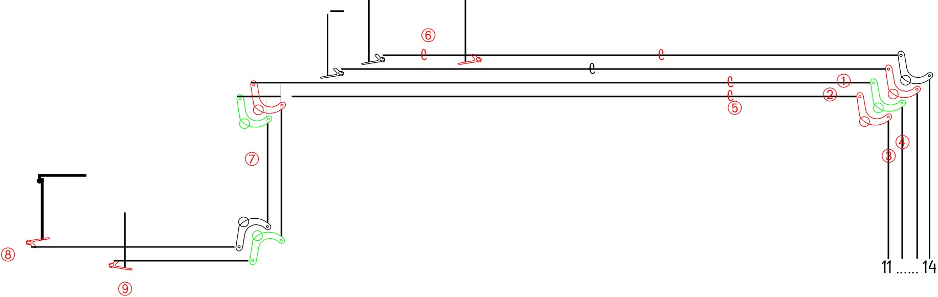 The rodding run from the signal box to 11, 12, 13 and 14. The rods shown (1) and (2) need lengthening by an inch, those shown (3) and (4) need shortening by an inch. Compensators are shown as 'C', those in red being worn, (5) is two compensators on a single, large base and (6) is shown (pictured) below. The cranks shown in green (high base accommodating crank) and red (low base accommodating crank) are to be replaced, with (7) shown below. Adjustable cranks are shown for 11 (8) and 12 (9). [Diagram: C. K. Hall]
Accommodating cranks are designed to allow two adjacent rods to turn through 90 degrees without colliding, see below.
 Two accommodating cranks (both to be replaced) plus the adjustable crank driving the FPL on the yard points, mounted on a single plate supported by large, buried concrete blocks. {Photo: C. K. Hall]
The worn cranks could be done over a weekend and so we arranged a handsignalman for Sunday 19th June, completing the work on Monday 20th, Sunday 26th and Monday 27th. The cranks concerned were those on the lead off for 11, 12 and 13 as well as three of the four cranks where the run for 11 and 12 crossed the track by the platform 1 Starting signal (marked (7) on the diagram). We also noted that the lead off cranks for 11 and 12 were striking the adjacent crank and stopping short when going reverse: this would require four new lengths of point rodding. We also noted that the rodding on 19 (Carriage Siding Safety) was buckling when reversed and needed an extra rodding support and a shorter clevis joint. Fortunately set L was rostered for the diesel footplate experience train on Sunday 12th and the brake could (just) accommodate five eighteen foot long lengths of point rodding and would not be in use by passengers. Delivery from Kidderminster to Bridgnorth was therefore easily arranged.
One of the worn compensators was coated in a mixture of oil, rainwater and grime, see below:
The compensator between 14A and 14B, shown as (6) on the diagram. It appears to be in a convenient place to receive contributions of locomotive ash. [Photo: C. K. Hall]
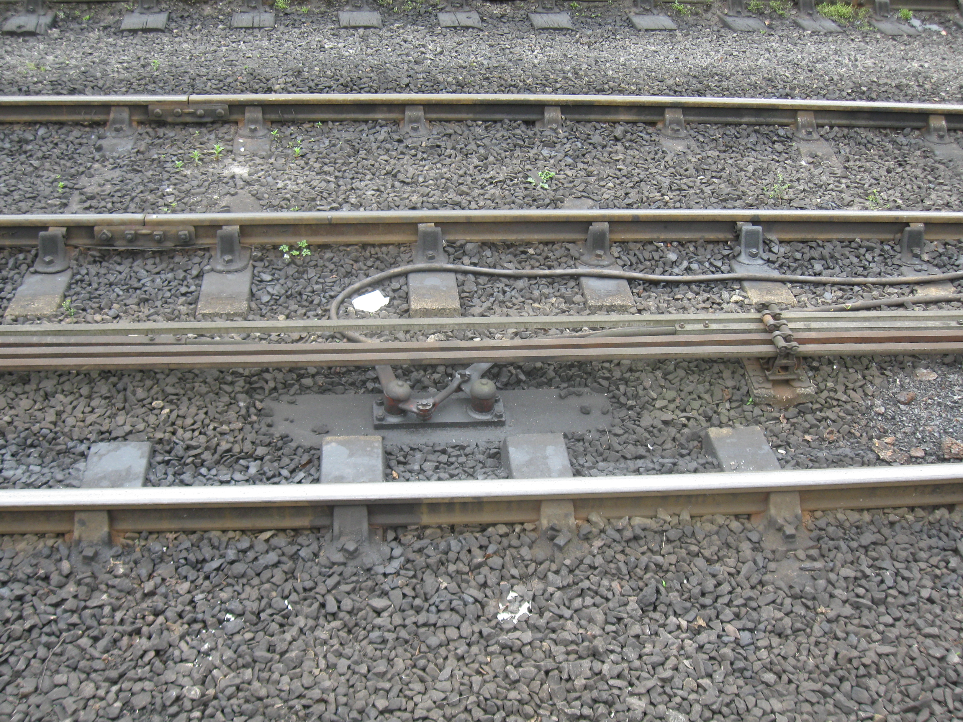
The purpose of a compensator is to reverse the direction of movement of point rodding to equalise the lengths of rodding in tension and compression so that temperature changes do not affect point movement. The picture below shows this more clearly:
 The compensator on 13 showing the machanism more clearly. [Photo: C. K. Hall]
Other faults we had attended included problems with 21 electric lock at Kidderminster (lock spring assembly misaligned and binding), a worn signal wire wheel on 28 (Down Main Starting) at Bewdley North (replaced using a refurbished spare from stock), electrical detection on 5/6 at Bewdley North not making up reliably (a small adjustment was all that was required - whilst doing that we found and recovered a disused crank base from earlier BR days) and problems with 1 electric lock at Bridgnorth (complete disassembly and clean).
A final reminder that this article and the photographs associated with it, as well as other information on Signal Engineering, can be viewed in full colour on the unofficial S&T (signals) web site at http://www.svrsig.org/ (or look for 'svrsig' on google).