http://www.svrsig.org/ diags/Diagrams.htm
The S&T Department kept records of the signalling equipment provided at each location and the G.W.R. and B.R.(W.R.) used a standard numbering sequence for the drawings (click here to see a list of locations for which information may be downloaded). The information was comprehensive and not in a form suitable for the Operating Department and so the information was summarised in the form of a box diagram and lever leads for presentation to the signalman. There are many sources for the information on box diagrams and lever leads, as these can easily be photographed during a visit to the signal box concerned. It is less easy to come by techncial documents, particularly because they were kept updated as the equipment was removed and rationalised and often only a skeleton layout remained on closure of the box.
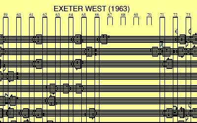
The principal item - the starting point for design work - is the locking sketch. This is a scale drawing of the area controlled by the signal box showing the track layout. Onto this is drawn the position of each signal. The critieria for placing of signals followed 'custom and practice' and the Signalling Record Society have published Signalling Papers, describibg Great Western practice in this area. Such information as to whether the signal aspect is repeated in the signal box (depending whether it can be seen from the box, although dummies with stab detection were not normally repeated), whether it has red or white lights in the stop aspect (practice on this varied - a white light did not necessarily convey permission to pass at danger for routes to which it did not apply - some diagrams in B.R. (W.R.) times had a 'W' suffix on the diagram to indicate a white light in a disc signal) and its distance from the box. It provides nearly all the information needed to create the box diagram which is displayed in the signal box.
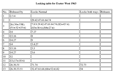
The box diagram or locking sketch, plus the operational input (a knowledge of which shunting routes need to be signalled and the traffic to be handled) allows the next design step - the locking table. This shows the necessary locking between each lever to satisfy the mechanical locking principles for the layout concerned. From this the lever leads - the pulling sequence to permit a particular lever to be reversed - can be generated so that each lever is numbered (to correspond with the box diagram), named (so that the signal or point has a defined name when operational messages have to be conveyed) and the pulling sequence identified (a reminder of the locking provided and which routes apply from a particular signal)
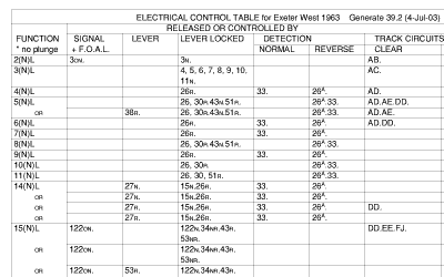
Under the floor the mechanical locking requirements are translated into a diagrammatic chart of the locking appropriate to the particular frame design - for example G.W. 3-bar vertical tappet. This chart is often called a 'dog chart'. Additional locking is sometimes needed and an electrical control table summarises the functions that are to be locked and the conditions required for release. Out on the ground, detection is provided to confirm correct operation of facing points before the relevant signal can be cleared - the mechanical and electrical detection requirements are identified in a detection schedule (the locking sketch normally shows which detection is mechanical and which electrical). Relevant circuit diagrams identify the components and wiring, specifying exactly the wire terminations and equipment required.
Standard B.R.(W.R.) practice was to number these drawings with an 'S'-series number identifying the signal box or location uniquely and a suffix identifying the particular drawing. This 'slot reference' identified a 'pigeonhole' containing all the relevant documents at Reading. A brief summary is given below.
| Technical drawing numbers | |
| Sxxxx/1 | Record of amendments |
| Sxxxx/2 | Locking sketch |
| Sxxxx/3 | Mechanical locking table |
| Sxxxx/4 | Detection table |
| Sxxxx/5 | Electrical control table |
| Sxxxx/6 | Dog chart |
| Sxxxx/7 | Lever leads |
| Sxxxx/8 | Lever lock and contact schedule |
| Sxxxx/9 | Electrical reference sheet |
| Sxxxx/10 | Signal box internal wiring diagrams and layout |
| Sxxxx/11 | External functions - location wiring etc. |
| Sxxxx/12 | Signal box diagram |
| Sxxxx/13 | Colour light signalling aspect sequence chart |
When the 'slot references' were created in 1957, the 'record of amendments' was used to record recent and any further changes and took over this function from more detailed amendment boxes on the individual drawings. It is thus a valuable record of the changes over the years in B.R. (W.R.) ownership. Many changes that might affect the box diagram, such as removal of sidings or connections, would be made by another Department, such as the Permanent Way Department - changes by the Signal Engineering Department might be confined to bolting one or two levers normal and to disconnect and remove the connections to unused levers under the box. The 'dog chart' might be left until a later date and unused levers simply painted white. In due course it was G.W. practice to remove unused levers and the associated locking but this was often much later. Changes such as removal of F.P.L. bars and provision of track circuits in lieu of them would normally require locking changes - the 'each way' locking of F.P.L. levers in rear of signals could be removed for example.
A number of box diagrams and other documentation may be downloaded - a list of the boxes for which such information is available is given below. Click on one of the links for further information.
| 'S'-series ref. | Signal box | Information available |
| S 13 | Acton Yard | Dog chart, mechanical locking table and lever leads (February 1958, December 1958, 1967 and 1969). |
| S 44 | Taplow | Dog chart and mechanical locking table (December 1946, September 1955). |
| S 165 | Didcot East Junction | Dog chart and mechanical locking table (October 1958). |
| S 176 | Morris Cowley | Dog chart and mechanical locking table (1954 and June 1961). |
| S 186 | Colthrop Crossing | Dog chart and mechanical locking table, showing proposed changes in 1971. |
| S 190 | Newbury Racecourse | Dog chart and mechanical locking table, showing the position at June 1963 and February 1965. |
| S 191 | Newbury East Junction | Dog chart and mechanical locking table, showing the position at February 1950. |
| S 220 | Hinksey South | Dog chart and mechanical locking table (1941). |
| S 223 | Hinksey North | Dog chart and mechanical locking table (1942 and 1946). |
| S 224 | Oxford Station South | Dog chart and mechanical locking table (1947). |
| S 225 | Oxford Station North | Dog chart, box diagram and mechanical locking table (1930 and 1953). |
| S 830 | Exeter East | Box diagram (for circa 1950s) as well as the mechanical locking table and the dog chart. |
| S 833 | Exeter West | Box diagram (for 1959, 1963 and 1970) as well as the mechanical locking table, the lever leads, the electrical control table and the dog chart. |
| S1061 | Par Station | Box diagram and locking table (for 1979), also dog chart and locking table (for 1962). |
| S1063 | St Austell | Box diagram, dog chart and locking table (for 1968). |
| S1073 | Penwithers Junction | Box diagram and locking table (for 1957). |
| S1086 | St. Erth | Box diagram (for 1941 and 1964) plus dog chart and associated locking table for 1941. |
| S1400 | Radyr Junction | Box diagram (for 1961, 1984 and 1987) as well as the mechanical locking table, the lever leads and the dog chart for 1987. |
| S1495 | Pengam Junction | Dog chart for 1951. |
| S1825 | Resolven East | Box diagram for 1950 as well as the mechanical locking table and the dog chart. |
| S1830 | Neath & Brecon Junction | Box diagram for 1956 and 1969. |
| S2115 | Morlais Junction | Dog chart and mechanical locking table (June 1961). |
| S2248 | Rotherwas Junction | Locking sketch, box diagram, dog chart, mechanical locking table, detection schedule, electrical control table and lever leads for June 1958, with some earlier information for 1925 and 1929. |
| S2647 | Bewdley North | Box diagram, mechanical locking table and dog chart as at 1956. |
| S2838 | Handsworth Junction | Box diagram circa 1950. |
| S2883 | Smethwick Junction | Box diagram circa 1950. |
| S2884 | Oldbury & Langley Green East | Box diagram circa 1950. |
| S2885 | Oldbury & Langley Green Middle | Box diagram circa 1950. |
| S2886 | Oldbury & Langley Green West Crossing | Box diagram circa 1950. |
| S2887 | Rowley Regis & Blackheath | Box diagram circa 1950. |
| S2888 | Old Hill Junction | Box diagram circa 1950. |
| S2889 | Cradley East | Box diagram circa 1950. |
| S2890 | Cradley West | Box diagram circa 1950. |
| S2891 | Lye | Box diagram circa 1950. |
| Sxxxx | Timmis Siding | Box diagram circa 1950. |
| S2894 | Oldbury Goods | Box diagram circa 1950. |
| S2895 | Halesowen | Box diagram circa 1950. |
| S2899 | Cox's Lane | Box diagram circa 1950. |
| S2900 | Windmill End Junction | Box diagram circa 1950. |
| S2903 | Stourbridge Junction South | Box diagram circa 1950. |
| S2904 | Stourbridge Junction Middle | Box diagram circa 1950. |
| S2905 | Stourbridge Junction North | Box diagram circa 1950. |
| S2906 | Stourbridge Junction Engine House | Box diagram circa 1950. |
| S2909 | Kingswinford Junction North | Box diagram circa 1950. |
| S2910 | Round Oak South | Box diagram circa 1950. |
| S2911 | Round Oak North | Box diagram circa 1950. |
| S2913 | Blowers Green Sidings | Box diagram circa 1950. |
| S2914 | Blowers Green Junction | Box diagram circa 1950. |
| S2915 | Dudley South | Box diagram circa 1950. |
| S2916 | Dudley North | Box diagram circa 1950. |
| S2917 | Tipton Junction | Box diagram circa 1950. |
| S2918 | Princes End & Coseley | Box diagram circa 1950. |
| S2927 | Pensnett | Box diagram circa 1950. |
| S3243 | Afon Wen | Sketches of box diagram before and after alterations in November 1924. |
 Exeter West (1963)
 | ||

|

|

|
For Acton Yard and Rotherwas Junction, a demonstration of how the locking operates is provided above in 'animated gif' files which can be viewed on all computer platforms. An example of GW 3 bar locking (Rotherwas Junction) and of GW 5 bar locking (Acton Yard) is shown during a sequence of shunting movements in which the mechanical locking of the frame operates as the levers are moved.
To make the demonstration as authentic as possible I decided to illustrate the locking using original design drawings and documentation. Boxes now long demolished were chosen to avoid questions of proprietary information. A computer simulation allowing different lever pulling sequences to be tried is available to be downloaded. It features Rotherwas Junction, Morlais Junction and Acton Yard.
I obtained a complete set of drawings for Rotherwas Junction (near Hereford), a partial set of drawings for Morlais Junction (near Pontardulais) and a complete set of drawings for Acton Yard. The purpose of the different documents is as follows:
The track layout is shown on the locking sketch, indicating the position of all points and signals, numbered to correspond to the levers in the frame, the names of running lines and sidings are included as well as other useful information such as distances, a note of which signals must be repeated in the box, fouling bars etc. It would also indicate which signals were to be provided with electric locks (e.g. line clear release, track circuit controls, electrical signal leads etc.). It would be kept updated with any changes - e.g. the drawing for Rotherwas Junction had a note that a 'Line Clear' release had been added to the up starting signal in 1932. The locking sketch thus provides the basic information from which the design of the interlocking can be produced.
The locking table is then drawn up to describe the functions of the mechanical locking (i.e. which lever should lock which lever) required to implement the mechanical locking principles as they apply to the particular location. Most (if not all) of the information needed to determine the necessary functions is on the locking sketch. In some cases, for example shunting signals which may read over several routes, further clarification may be necessary. The mechanical locking is designed independently of any electrical locking that may be provided.
The locking table is arranged to show, for each lever, which levers release them, which levers are locked normal by them and which levers are locked 'each way' by them. For example if lever 19 releases lever 17 then lever 17 cannot be reversed until lever 19 has been reversed and this would be shown in the table as 17 released by 19.
The six main mechanical locking principles, as specified in the 'Brown Book'
are as follows:
(i) a signal cannot be cleared unless the point levers are set correctly;
(ii) a signal cannot be cleared unless levers controlling facing point
locks, where provided, have been operated to bolt the points in place;
(iii) signals for conflicting movements cannot be cleared simultaneously;
(iv) a distant signal cannot be cleared unless all stop signals to which
it applies have been cleared;
(v) point levers are locked with other point levers so that conflicting
routes cannot be set;
(vi) signal levers lock trailing points in rear (in either position).
All of these six main principles relate to the mechanical locking of the lever frame itself. Their application varied in matters of detail region to region - for example principle (ii) was quoted in the S.R. Brown Book as: signal levers precede the levers working bolts as far as 100 yards ahead of the next signal.
A schedule of the detection to be provided, and whether electrical or mechanical, is then prepared to cover all signalled movements over points in the facing direction. There are some exceptions - shunting signals which read over facing points which can be bolted in either position would not normally be provided with detection. Otherwise the detection proves that the point blades (and F.P.L.) have responded correctly to the lever before the signal can be cleared.
The electrical control table is then drawn up to describe the functions required of the various control circuits including electric locks on certain levers as well as block circuits and signal functions.
Once the locking functions are specified, the lever leads can be prepared - this is the only 'interface' with the signalman who will operate the box and it indicates the lever number, the function it performs and the pulling sequence for the levers which must be reversed to release it.